Intro - Basic Networking Concepts
This blog post outlines a handful of basic networking concepts, tools, and components that are important to understand for any Networking, Infrastructure, DevOps, or Site Reliability Engineer. It is not a comprehensive list, nor am I going to go in depth into each subject, however I have collected quite a few notes over the years, and wanted to aggregate and consolidate them into one place.
Concepts Covered
TCP vs UDP
Both TCP and UDP use a numerical identifier for the data structures of the endpoints for host-to-host communications. Such an endpoint is known as a port and the identifier is the port number. TCP is a connection-oriented protocol and UDP is a connection-less protocol.
Transmission Control Protocol (TCP)
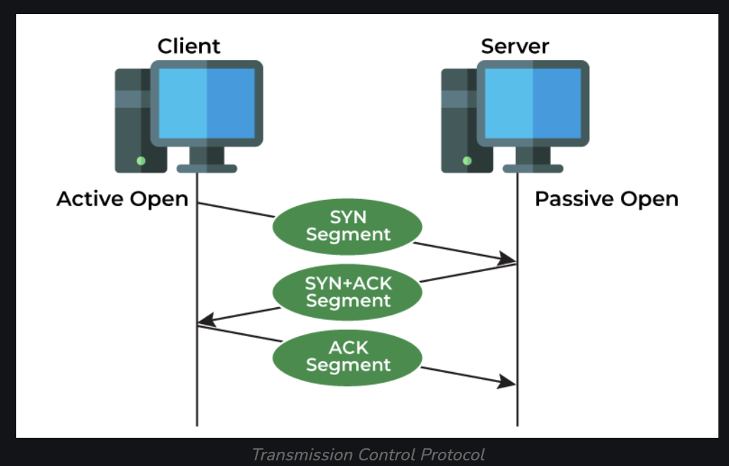
TCP directs packets to a specific application on a computer using a port number, and works with the IP, which defines how computers send packets of data to each other. TCP defines how to establish and maintain a network conversation through which application programs can exchange data. The Transmission Control Protocol (TCP) is one of the main protocols of the Internet protocol suite. TCP originated in the initial network implementation in which it complemented the Internet Protocol (IP). Hence, it is broadly referred to as TCP/IP.
-
The stages of establishing a TCP connection:
- 1) LISTEN – Server is listening on a port, such as HTTP
- 2) SYNC-SENT – Sent a SYN request, waiting for a response
- 3) SYN-RECEIVED – (Server) Waiting for an ACK, occurs after sending an ACK from the server
- 4) ESTABLISHED – 3 way TCP handshake has completed
User Datagram Protocol (UDP)
User Datagram Protocol Communications protocol that is primarily used for establishing low-latency and loss-tolerating connections between applications on the internet. It speeds up transmissions by enabling the transfer of data before an agreement is provided by the receiving party.
(Extra) IP (Internet Protocol)
IP directs packets to a specific computer using an IP address. IP is at Layer 3 (Transport) of the OSI model (see OSI Model section below), while TCP and UDP are at Layer 4 (Transport).
TCP vs UDP
Some key differences between TCP and UDP:
NAT Gateway
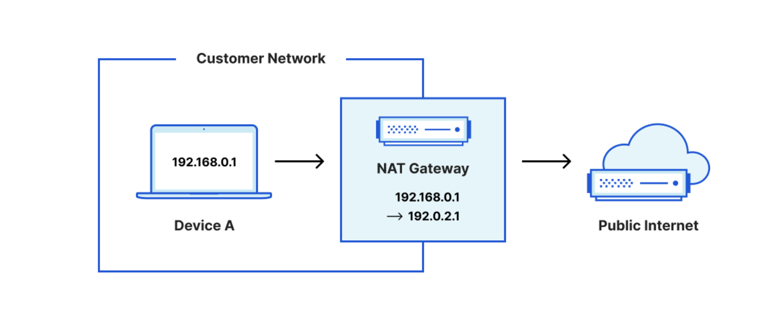
Fundamentally, a NAT Gateway allows instances with no public IPs to access the internet. A NAT gateway is a Network Address Translation (NAT) service. Instances in a private subnet can connect to services outside your VPC but external services cannot initiate a connection with those instances. Many times NAT gateways are classified into Internet NAT gateways and Virtual Private Cloud (VPC) NAT gateways. Internet NAT gateways provide NAT services for public IP addresses, while VPC NAT gateways provide NAT services for private IP addresses. NAT Gateways provide.
It is easiest to think of NAT Gateways in terms of traffic flow. NAT gateways intercept Egress (outgoing) traffic. Or, in other words, traffic coming from inside a private network to the public network or internet.
They will perform IP Translation so that the downstream service at the receiving end of the request will see the request coming from the NAT Gateway, not the service which has a private IP in a private network.
Internet Gateway
Fundamentally, an Internet Gateway (IGW) allows instances with public IPs to access the internet.
An Internet gateway is a network "node" that connects two different networks that use different protocols (rules) for communicating. In the most basic terms, an Internet gateway is where data stops on its way to or from other networks. Thanks to gateways, we can communicate and send data back and forth with each other.
Internet GW allows both inbound and outbound access to the internet. Which differs from a NAT Gateway in that the NAT Gateway only allows outbound access. Thus, an Internet GAteway allows instances with public IPs to access the internet whereas NAT Gateway allows instances with private IPs to access internet.
Routers are often Internet gateways. They are a piece of hardware that essentially connects your computer to the Internet. In home networks, it is usually something that comes with software you can install on one computer and then connect other computers to as well. Then everyone connected to your router can connect to the Internet through your ISP. While a router can be connected to more than two networks at a time, this is usually not the case for routers used at home.
In short, an Internet gateway is one of the ways that information is sent and delivered to us as we use the Internet.
It is what gives us the ability to access other networks to view web pages, initiate downloads or uploads, buy things online, and more.

Default Gateway
A default gateway in simple terms is device that forwards data from one network to another. It is a node in a computer network that forwards traffic to other networks when no other route matches the destination IP address of a packet. It's the first path that information takes between systems, and it's often called the gateway. For example, in a home office with wireless internet, the router is the default gateway. In fact, the majority of time the default gateway is going to be a router.
RouteTable and Router
A routing table is a set of rules, often viewed in table format, that is used to determine where data packets traveling over an Internet Protocol (IP) network will be directed. All IP-enabled devices, including routers and switches, use routing tables.
Subnet
In the most basic sense, a subnet is a logical subdivision of an IP network. The practice of dividing a network into two or more networks is called subnetting. Computers that belong to a subnet are addressed with an identical most-significant bit-group in their IP addresses.
Purpose: To improve network performance. Running a vast amount of network devices on the same subnet can abstruse and complicate the network, especially if there's a lot of broadcast traffic.
Virtual Private Network (VPN)
A Virtual Private Network, or VPN, is a tool that implements a data and traffic tunneling feature. It extends a private network across a public network, and enables users to send and receive data across shared or public networks as if their computing devices were directly connected to the private network. It is a mechanism for creating a secure connection between a computing device and a computer network, or between two networks, using an insecure communication medium such as the public Internet. One downside to note is that depending on VPN options, geo location, and internet bandwidth, some VPN options may make your connection speed decrease slightly, sometimes by 10%. However, the upside of a VPN traditionally security. As a VPN is creating a point-to-point tunnel that encrypts your personal data, masks your IP address, and lets you sidestep website blocks and firewalls on the internet.
As a simple example of a use case for a VPN, say you are in Mexico and you want to access Star Sports' grid of live games, debate shows and highlights of your favorite leagues. You can establish connection with the VPN of your choice, select an Indian server that provides you with an Indian VPN address and the service will think your connection is coming from India, not from Mexico.
An IPSec tunnel allows for the implementation of a virtual private network (VPN) which an enterprise may use to securely extend its reach beyond its own network to customers, partners and suppliers. There are several types of VPN protocols for tunneling, or transmitting, data over the Internet. For example, most eCommerce sites use Secure Sockets Layer (SSL) and Transport Layer Security (TLS). Some networks utilize Secure Shell (SSH), and others use Layer 2 Tunneling Protocol (L2TP). Compared to these various types of “normal” tunnels, IPSec provides the most robust cryptographic security.
IPsec VPN is one of two common VPN protocols, or set of standards used to establish a VPN connection. IPsec is set at the IP layer, and it is often used to allow secure, remote access to an entire network (rather than just a single device). This inability to restrict users to network segments is a common concern with this protocol.
IPsec VPNs come in two types:
DNS
The world of computers works in 1's and 0's. Computers don't recognize names, they recognize numbers (more specifically binary). However, we as humans do not operate this way. If we were to speak the same langauge as computers, you would have to memorize all the IPs of your favorite webistes; and when you wanted to navigate to them, type that IP in the URL bar. DNS was created to solve this issue. DNS (Domain Name System) is how we map an IP address to recognizable host names. So, instead of having to memorize 192.186.60.0 if you wanted to go to google.com for example, you can just type in https://www.google.com and be taken there.
DNS Records
DNS records (aka zone files) are instructions that live in authoritative DNS servers and provide information about a domain including what IP address is associated with that domain and how to handle requests for that domain. Probably the most common, (and at the least the easiest to understand) is the A Record. An A record maps a domain name to the IP address (Version 4) of the computer hosting the domain. An A record uses a domain name to find the IP address of a computer connected to the internet. The A in A record stands for Address. Whenever you visit a web site, send an email, connect to Twitter or Facebook, or do almost anything on the Internet, the address you enter is a series of words connected with dots. Here are the other most common DNS records:
TTL limits how long data can “live” in an IP network. Every packet of data is assigned a TTL value. Every time a data packet reaches a hop, the TTL value is decreased by one. Another key element to understand is “round-trip time” (RTT). Traceroute ensures each hop on the way to a destination device drops a packet and sends back an ICMP error message. This means traceroute can measure the duration of time between when the data is sent and when the ICMP message is received back for each hop—giving you the RTT value for each hop.
An example of how to run traceroute:
What happens when you type in address to URL
The browser checks the cache for a DNS (domain name system) record to find the corresponding IP address. To find the DNS record, the browser checks four caches.
The purpose of a DNS query is to search multiple DNS servers on the internet until it finds the correct IP address for the website. This type of search is called a recursive search since the search will repeatedly continue from a DNS server to a DNS server until it either finds the IP address we need or returns an error response saying it was unable to find it.

OSI Model
The open systems interconnection (OSI) model is a conceptual model created by the International Organization for Standardization which enables diverse communication systems to communicate using standard protocols.
Essentially, the OSI provides a standard for different computer systems to be able to communicate with each other.
The OSI Model can be seen as a universal language for computer networking.
It is based on the concept of splitting up a communication system into seven abstract layers, each one stacked upon the last.
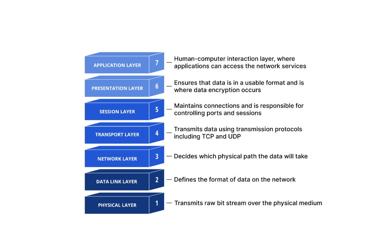
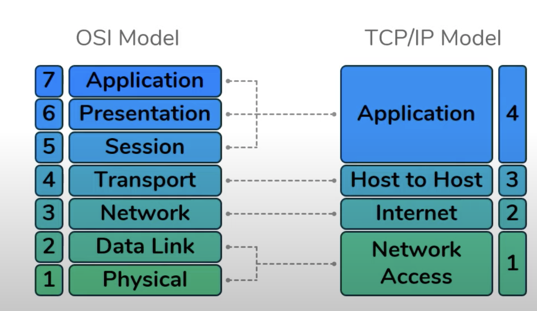
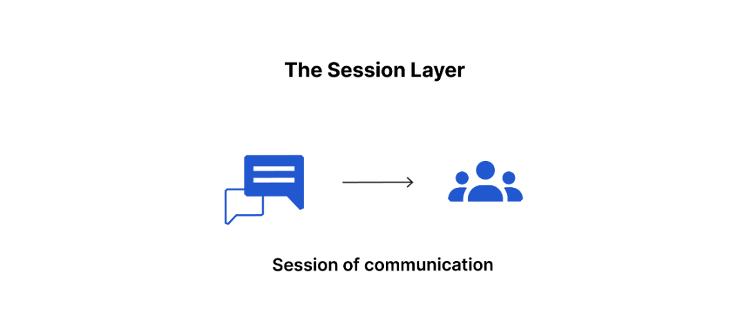
Important to note that when the OSI model was first created, the top three layers (Session, Presentation, and Application) had a specific function that was independent from the rest. Howver, currently the distinction between these layers can be somewhat vague. Every application is infact free to impliment the functions of Layer 5, 6, and 7 as they choose. Therefor, these three layers are often considered as a single universal "Application" layer. In fact, the other popular internet communication model, called the TCP/IP Model, does exactly that.


Hub
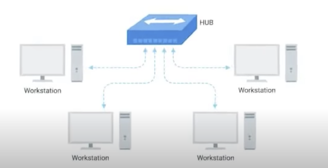
Allows many computers to communicate with each other at once. A Hub (or Ethernet hub, active hub, network hub, repeater hub, multiport repeater) is a network hardware device for connecting multiple Ethernet devices together and making them act as a single network segment.
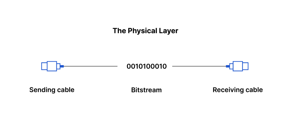
It has multiple input/output (I/O) ports, in which a signal introduced at the input of any port appears at the output of every port except the original incoming. A hub works at the physical layer.
A layer 1 network device such as a hub transfers data but does not manage any of the traffic coming through it.
Any packet entering a port is repeated to the output of every other port except for the port of entry.
Specifically, each bit or symbol is repeated as it flows in. A repeater hub can therefore only receive and forward at a single speed.
Dual-speed hubs internally consist of two hubs with a bridge between them. Since every packet is repeated on every other port, packet collisions affect the entire network, limiting its overall capacity.
Modem
Connects LANs to the internet. “Modulator” Modulates or transforms Digital to analogue and vice versa. A modem transmits data by modulating one or more carrier wave signals to encode digital information, while the receiver demodulates the signal to recreate the original digital information. The goal is to produce a signal that can be transmitted easily and decoded reliably. Modems can be used with almost any means of transmitting analog signals, from light-emitting diodes to radio.
Switch
A network switch (also called switching hub, bridging hub, and, by the IEEE, MAC bridge) is networking hardware that connects devices on a computer network by using packet switching to receive and forward data to the destination device. A network switch is a multiport network bridge that uses MAC addresses to forward data at the data link layer (layer 2) of the OSI model. Some switches can also forward data at the network layer (layer 3) by additionally incorporating routing functionality. Such switches are commonly known as layer-3 switches or multilayer switches. Unlike repeater hubs, which broadcast the same data out of each port and let the devices pick out the data addressed to them, a network switch learns the Ethernet addresses of connected devices and then only forwards data to the port connected to the device to which it is addressed. Switches are most commonly used as the network connection point for hosts at the edge of a network. In the hierarchical internetworking model and similar network architectures, switches are also used deeper in the network to provide connections between the switches at the edge. The network switch plays an integral role in most modern Ethernet local area networks (LANs). Mid-to-large-sized LANs contain a number of linked managed switches. Small office/home office (SOHO) applications typically use a single switch, or an all-purpose device such as a residential gateway to access small office/home broadband services such as DSL or cable Internet. In most of these cases, the end-user device contains a router and components that interface to the particular physical broadband technology.
Control Plane vs Data Plane
In networking, a plane is an abstract conception of where certain processes take place. The term is used in the sense of "plane of existence." The two most commonly referenced planes in networking are the control plane and the data plane (also known as the forwarding plane).
The control plane is the part of a network that controls how data packets are forwarded — meaning how data is sent from one place to another. The process of creating a routing table, for example, is considered part of the control plane. Routers use various protocols to identify network paths, and they store these paths in routing tables.
In contrast to the control plane, which determines how packets should be forwarded, the data plane actually forwards the packets. The data plane is also called the forwarding plane.
In Routing... control plane refers to the all functions and processes that determine which path to use to send the packet or frame. Control plane is responsible for populating the routing table, drawing network topology, forwarding table and hence enabling the data plane functions. Means here the router makes its decision. In a single line it can be said that it is responsible for How packets should be forwarded.
In Routing... data plane refers to all the functions and processes that forward packets/frames from one interface to another based on control plane logic. Routing table, forwarding table and the routing logic constitute the data plane function. Data plane packet goes through the router and incoming and outgoing of frames are done based on control plane logic. Means in single line it can be said that it is responsible for moving packets from source to destination. It is also called the Forwarding plane.
Network topology refers to the way data flows in a network. The control plane establishes and changes network topology. Again, think of the stoplights that function at the intersections of a city. Network topology is like the way that the roads are arranged, and the computing devices within the network are like the destinations that those roads lead to
Virtual LAN or VLAN (Virtual Local Area Network)
A virtual LAN (VLAN) is any broadcast domain that is partitioned and isolated in a computer network at the data link layer (OSI layer 2). LAN is the abbreviation for local area network and in this context virtual refers to a physical object recreated and altered by additional logic. VLANs work by applying tags to network frames and handling these tags in networking systems – creating the appearance and functionality of network traffic that is physically on a single network but acts as if it is split between separate networks. In this way, VLANs can keep network applications separate despite being connected to the same physical network, and without requiring multiple sets of cabling and networking devices to be deployed.
VLANs allow network administrators to group hosts together even if the hosts are not directly connected to the same network switch. Because VLAN membership can be configured through software, this can greatly simplify network design and deployment. Without VLANs, grouping hosts according to their resource needs the labor of relocating nodes or rewiring data links. VLANs allow devices that must be kept separate to share the cabling of a physical network and yet be prevented from directly interacting with one another. This managed sharing yields gains in simplicity, security, traffic management, and economy.
For example, a VLAN can be used to separate traffic within a business based on individual users or groups of users or their roles (e.g. network administrators), or based on traffic characteristics (e.g. low-priority traffic prevented from impinging on the rest of the network's functioning). Many Internet hosting services use VLANs to separate customers' private zones from one other, allowing each customer's servers to be grouped in a single network segment no matter where the individual servers are located in the data center. Some precautions are needed to prevent traffic "escaping" from a given VLAN, an exploit known as VLAN hopping. To subdivide a network into VLANs, one configures network equipment. Simpler equipment might partition only each physical port (if even that), in which case each VLAN runs over a dedicated network cable. More sophisticated devices can mark frames through VLAN tagging, so that a single interconnect (trunk) may be used to transport data for multiple VLANs. Since VLANs share bandwidth, a VLAN trunk can use link aggregation, quality-of-service prioritization, or both to route data efficiently.
Conntrack
Component of Netfilter used to track the state of connections to and from the machine.
Identifies connections as tuple:
What is A Port?
A port is a virtual point where network connections start and end. Ports are software-based and managed by a computer's operating system. Each port is associated with a specific process or service. Ports allow computers to easily differentiate between different kinds of traffic: emails go to a different port than webpages, for instance, even though both reach a computer over the same Internet connection.
Netstat
Netstat is a utility tool that displays network connections for Transmission Control Protocol, routing tables, and a number of network interface and network protocol statistics. The netstat command works in conjunction with the ifconfig command to provide a status condition of the TCP/IP network interface. The command netstat -in for example uses the -i flag to present information on the network interfaces while the -n flag prints the IP addresses instead of the host names.TLS (Transport Layer Security)
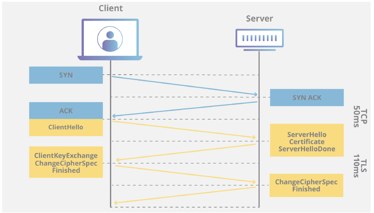
Transport Layer Security (TLS), the successor of the now-deprecated Secure Sockets Layer (SSL), is a cryptographic protocol designed to provide communications security over a computer network. Several versions of the protocol are widely used in applications such as email, instant messaging, and voice over IP, but its use as the Security layer in HTTPS remains the most publicly visible. The TLS protocol aims primarily to provide privacy and data integrity between two or more communicating computer applications. It runs in the application layer of the Internet and is itself composed of two layers: the TLS record and the TLS handshake protocols.
TLS evolved from a previous encryption protocol called Secure Sockets Layer (SSL), which was developed by Netscape. TLS version 1.0 actually began development as SSL version 3.1, but the name of the protocol was changed before publication in order to indicate that it was no longer associated with Netscape. Because of this history, the terms TLS and SSL are sometimes used interchangeably. HTTPS is an implementation of TLS encryption on top of the HTTP protocol, which is used by all websites as well as some other web services. Any website that uses HTTPS is therefore employing TLS encryption.
For a website or application to use TLS, it must have a TLS certificate installed on its origin server (the certificate is also known as an "SSL certificate" because of the naming confusion described above). A TLS certificate is issued by a certificate authority to the person or business that owns a domain. The certificate contains important information about who owns the domain, along with the server's public key, both of which are important for validating the server's identity.
IPsec Tunnel
IPsec tunnel mode is used between two dedicated routers, with each router acting as one end of a virtual "tunnel" through a public network. In IPsec tunnel mode, the original IP header containing the final destination of the packet is encrypted, in addition to the packet payload. To tell intermediary routers where to forward the packets, IPsec adds a new IP header. At each end of the tunnel, the routers decrypt the IP headers to deliver the packets to their destinations. An Internet Protocol Security (IPSec) tunnel is a set of standards and protocols originally developed by the Internet Engineering Task Force (IETF) to support secure communication as packets of information are transported from an IP address across network boundaries and vice versa. An IPSec tunnel allows for the implementation of a virtual private network (VPN) which an enterprise may use to securely extend its reach beyond its own network to customers, partners and suppliers.
There are several types of VPN protocols for tunneling, or transmitting, data over the Internet. For example, most eCommerce sites use Secure Sockets Layer (SSL) and Transport Layer Security (TLS). Some networks utilize Secure Shell (SSH), and others use Layer 2 Tunneling Protocol (L2TP). Compared to these various types of “normal” tunnels, IPSec provides the most robust cryptographic security.
CAP Theorem
Concept that a distributed database system can only have two of the three:
All nodes see the same data at the same time. Simply put, performing a read operation will return the value of the most recent write operation causing all nodes to return the same data. A system has consistency if a transaction starts with the system in a consistent state, and ends with the system in a consistent state.
In this model, a system can (and does) shift into an inconsistent state during a transaction, but the entire transaction gets rolled back if there is an error during any stage in the process. Imagine we have 2 different records ("Bulbasaur" and "Pikachu") at different timestamps. The output on the third partition is "Pikachu", the latest input. However, the nodes will need time to update and will not be Available on the network as often. The data is same in all the server nodes(leader or follower) no matter where you read it from (either node A or B) data is always identical implying the system has nearly instantaneous sync capabilities
Every request gets a response. (success/failure). Achieving availability in a distributed system requires that the system remains operational 100% of the time. Every client gets a response, regardless of the state of any individual node in the system.
This metric is trivial to measure: either you can submit read/write commands, or you cannot. Hence, the databases are time independent as the nodes need to be available online at all times. Unlike the previous example, we do not know if "Pikachu" or "Bulbasaur" was added first. The output could be either one. Hence why, high availability isn't feasible when analyzing streaming data at high frequency.
When dealing with modern distributed systems, Partition Tolerance is not an option. It's a necessity. Hence, we have to trade between Consistency and Availability. System continues to run, despite number of messages being delayed by the network between nodes.
A system that is partition-tolerant can sustain any amount of network failure that doesn't result in a failure of the entire network. Data records are sufficiently replicated across combinations of nodes and networks to keep the system up through intermittent outages. system continues to respond, even after some of the server nodes fail. Implies that the system maintains all the requests/responses function somehow.
CP [Consistency/Partition Tolerance] Systems
AP [Availability/Partition Tolerance] Systems
CA [Consistency/Availability] Systems
SRE Concepts - Monitoring, Alerting, Notifications
Very brief high level overview of monitoring and alerting, from the DevOps and SRE perspective. This is meant to just introduce these concepts, and provide a short foundational definition to each. These are vary large and important concepts, especially when running a distributed system at enterprise level. If interested in more detail into SRE, and curious the difference in SRE vs DevOps, see my blog post Core Principals of SRE (Site Reliability Engineering) and SRE vs DevOps.
Monitoring is the process of collecting, aggregating, and analyzing the metrics provided by the components in your environment by using a monitoring solution. A monitoring system enables you to gather statistics, store, centralize and visualize metrics, events, logs, and traces in real time. A good monitoring system enables you to see the bigger picture of what is going on across your infrastructure at any time, all the time, and in real time. Monitoring solutions enable you to sample or aggregate both current and historical data. While fresh metrics are essential for troubleshooting any new issues, they are also valuable when analyzed over longer periods of time. Doing this provides insight you can see only when you zoom out and see changes, patterns, and trends over time. Good monitoring solutions will make your job easier by providing you with out-of-the-box or customizable graphs and dashboards where you can instantly see how all your apps and services interact with each other. Instead of finding your way around tables, you can now understand what’s happening at a glance.
Alerting is the reactive element of a monitoring system that triggers actions whenever metric values change. Therefore, the most common and basic type of alert includes a threshold and an action the system needs to perform whenever alert rule conditions are met. Besides threshold-based alerts, monitoring systems often include anomaly detection-based alerting and heartbeat alerts. Alerts are often the main “interaction interface” DevOps engineers have with monitoring systems. While pretty dashboards are useful, too, you don’t want to have to look at them all the time to spot problems. You want to carry on with your life and work and be alerted when there is something you need to address.
There are two common outputs of alerts:
Notifications are the most common output of alerts. Their main purpose is to alert a human being to a problem, providing as much context along the way to help the person troubleshoot and solve problems faster. Effective alert notifications must contain enough information to paint a clear picture of what happened, where, and when so that engineers can easily and quickly understand the root cause and fix it. Automated actions are not as common in monitoring systems. They can be useful in situations when automated actions are safe to perform without human intervention. An example of such action may be an automated restart of a problematic service.
Certificates (SSL/ TLS) and the TLS Handshake
Digital document issued by a certificate authority that binds a public key to the identity of the certificate owner, thereby enabling the certificate owner to be authenticated. An identity certificate issued by a CA is digitally signed with the private key of the certificate authority.
A Certificate (also known as digital certificate, public key certificate, digital ID, or identity certificate) is a signed certificate that is obtained from a certificate authority by generating a certificate signing request (CSR). Signed certificate that is obtained from a certificate authority by generating a certificate signing request (CSR).
It typically contains:
The certificate authority analyzes the CSR fields, validates the accuracy of the fields, generates a certificate, and sends it to the requester. A certificate can also be self-signed and generated by any one of many tools available, such as IBM® Sterling Certificate Wizard or OpenSSL. These tools can generate a digital certificate file and a private key file in PEM format, which you can combine using any ASCII text editor to create a key certificate file.
An organization that issues digitally-signed certificates. The certificate authority authenticates the certificate owner's identity and the services that the owner is authorized to use, issues new certificates, renews existing certificates, and revokes certificates belonging to users who are no longer authorized to use them. The CA digital signature is assurance that anybody who trusts the CA can also trust that the certificate it signs is an accurate representation of the certificate owner.
Message sent from an applicant to a CA in order to apply for a digital identity certificate. Before creating a CSR, the applicant first generates a key pair, keeping the private key secret. The CSR contains information identifying the applicant (such as a directory name in the case of an X.509 certificate), and the public key chosen by the applicant. The CSR may be accompanied by other credentials or proofs of identity required by the certificate authority, and the certificate authority may contact the applicant for further information.
String of characters used as the private, “secret” part of a complementary public-private key pair. The symmetric cipher of the private key is used to sign outgoing messages and decrypt data that is encrypted with its complementary public key. Data that is encrypted with a public key can only be decrypted using its complementary private key. The private key is never transmitted and should never be shared with a trading partner.
String of characters used as the publicly distributed part of a complementary public-private key pair. The asymmetric cipher of the public key is used to confirm signatures on incoming messages and encrypt data for the session key that is exchanged between server and client during negotiation for an SSL/TLS session. The public key is part of the ID (public key) certificate. This information is stored in the key certificate file and read when authentication is performed.
Asymmetric cipher used by the client and server to encrypt data. It is generated by the SSL software. Trusted root certificate file (also known as root certificate file File that contains one or more trusted root certificates used to authenticate ID (public) certificates sent by trading partners during the Sterling Connect:Direct® protocol handshake.
A cryptographic key exchange algorithm that enables you to encrypt and decrypt files and messages with the SSL or TLS protocol.
A level of authentication that requires the client to authenticate its identity to the server by sending its certificate.
File that contains the encrypted private key and the ID (public key) certificate. This file also contains the certificate common name that can be used to provide additional client authentication.
Passphrase used to access the private key.
Digital document that is self-issued, that is, it is generated, digitally signed, and authenticated by its owner. Its authenticity is not validated by the digital signature and trusted key of a third-party certificate authority. To use self-signed certificates, you must exchange certificates with all your trading partners.
The industry-standard way to add encryption for data in motion is to use TLS (the successor to SSL). There are many examples online explaining how TLS works, but here are the basics:
How does that "proof" work? Your web browser will attempt to validate the TLS cert in two ways:
Now your client/browser has:
When talking about TLS and Trust Domains, I think it would be appropriate to briefly touch on SPIFFE as well. SPIFFE, the Secure Production Identity Framework for Everyone, is a set of open-source standards for securely identifying software systems in dynamic and heterogeneous environments. Systems that adopt SPIFFE can easily and reliably mutually authenticate wherever they are running. (Example: Istio) It is a set of open-source specifications for a framework capable of bootstrapping and issuing identity to services across heterogeneous environments and organizational boundaries. The heart of these specifications is the one that defines short lived cryptographic identity documents – called SVIDs via a simple API. Workloads can then use these identity documents when authenticating to other workloads, for example by establishing a TLS connection or by signing and verifying a JWT token.
A SPIFFE ID is a string that uniquely and specifically identifies a workload. SPIFFE IDs may also be assigned to intermediate systems that a workload runs on (such as a group of virtual machines). SPIFFE IDs are a Uniform Resource Identifier (URI) which takes the following format: spiffe://trust domain/workload identifier. The workload identifier uniquely identifies a specific workload within a trust domain.
The trust domain corresponds to the trust root of a system. A trust domain could represent an individual, organization, environment or department running their own independent SPIFFE infrastructure. All workloads identified in the same trust domain are issued identity documents that can be verified against the root keys of the trust domain.
Border Gateway Protocol (BGP)
BGP is a dynamic Routing protocol used to manage how packets get routed between edge routers on the internet. It is a set of rules that allows networks to communicate and exchange routing information. When someone submits data via the Internet, BGP is responsible for looking at all of the available paths that data could travel and picking the best route, which usually means hopping between autonomous systems. BGP is the protocol that makes the Internet work by enabling data routing. When a user in Singapore loads a website with origin servers in Argentina, BGP is the protocol that enables that communication to happen quickly and efficiently.
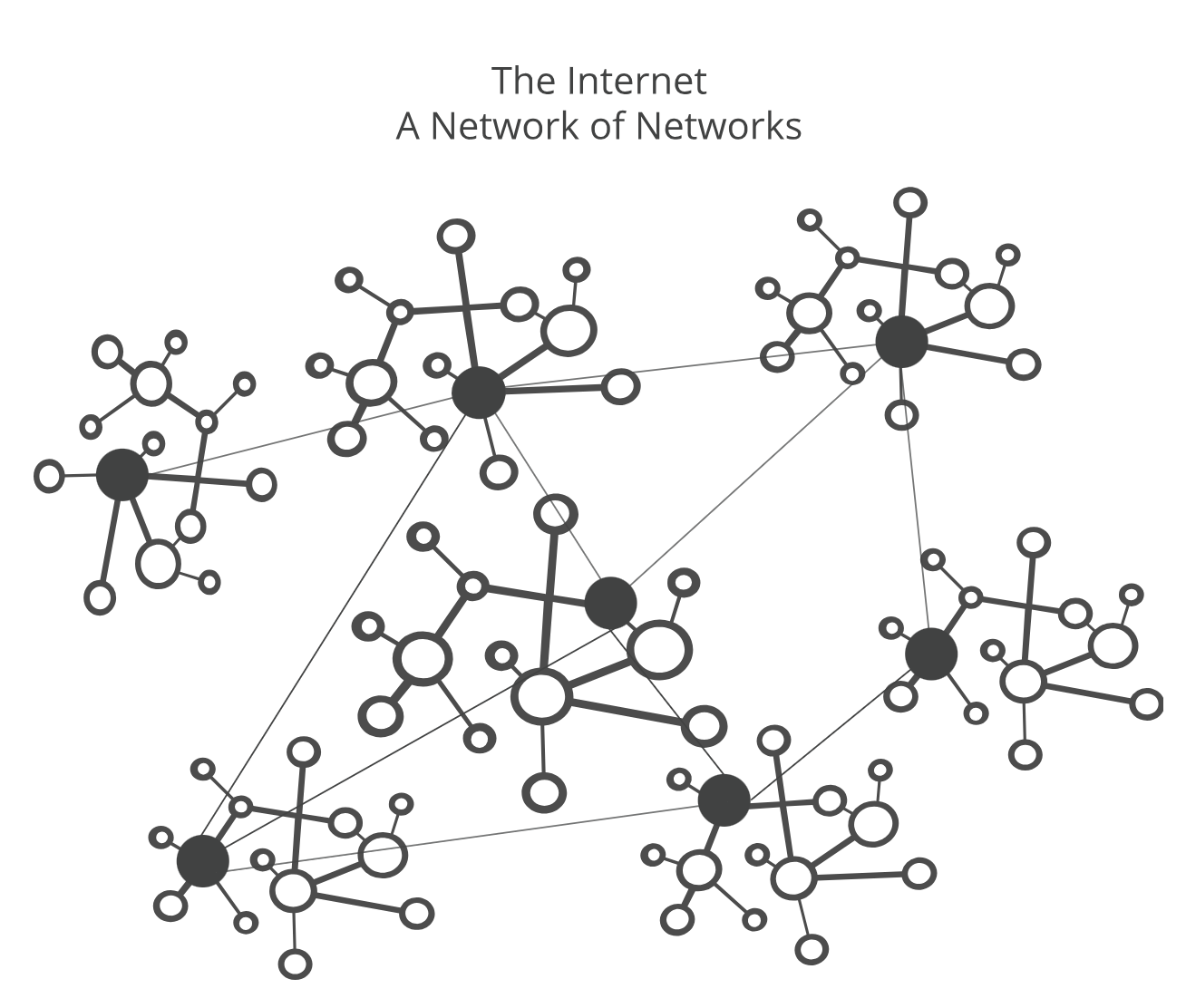
The Internet is a network of networks. It is broken up into hundreds of thousands of smaller networks known as autonomous systems (ASes). Each of these networks is essentially a large pool of routers run by a single organization.
Each network is assigned a BGP ASN (autonomous system number) to designate a single administrative entity or corporation that represents a common and clearly defined routing policy on the internet. BGP is a standardized exterior gateway protocol designed to exchange routing and reachability information among autonomous systems (AS) on the Internet. BGP is classified as a path-vector routing protocol, and it makes routing decisions based on paths, network policies, or rule-sets configured by a network administrator.
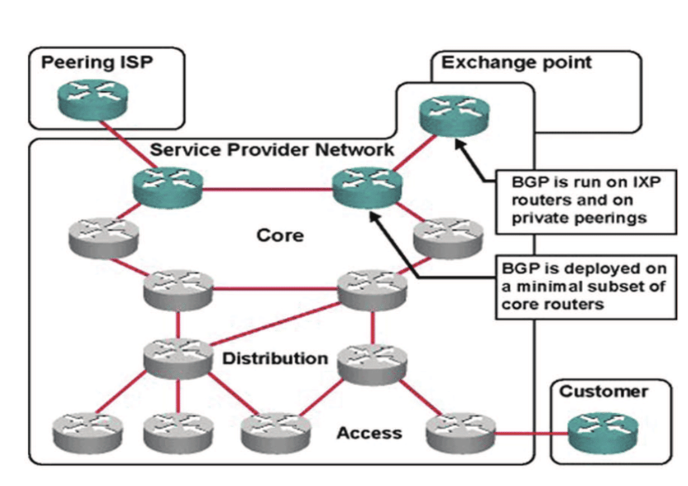
For routing, BGP determines the best path for data to travel between networks, considering all available options. BGP enables networks to announce themselves as destinations or routes to destinations, and allows network operators to control traffic flow, optimize bandwidth, and improve network performance.
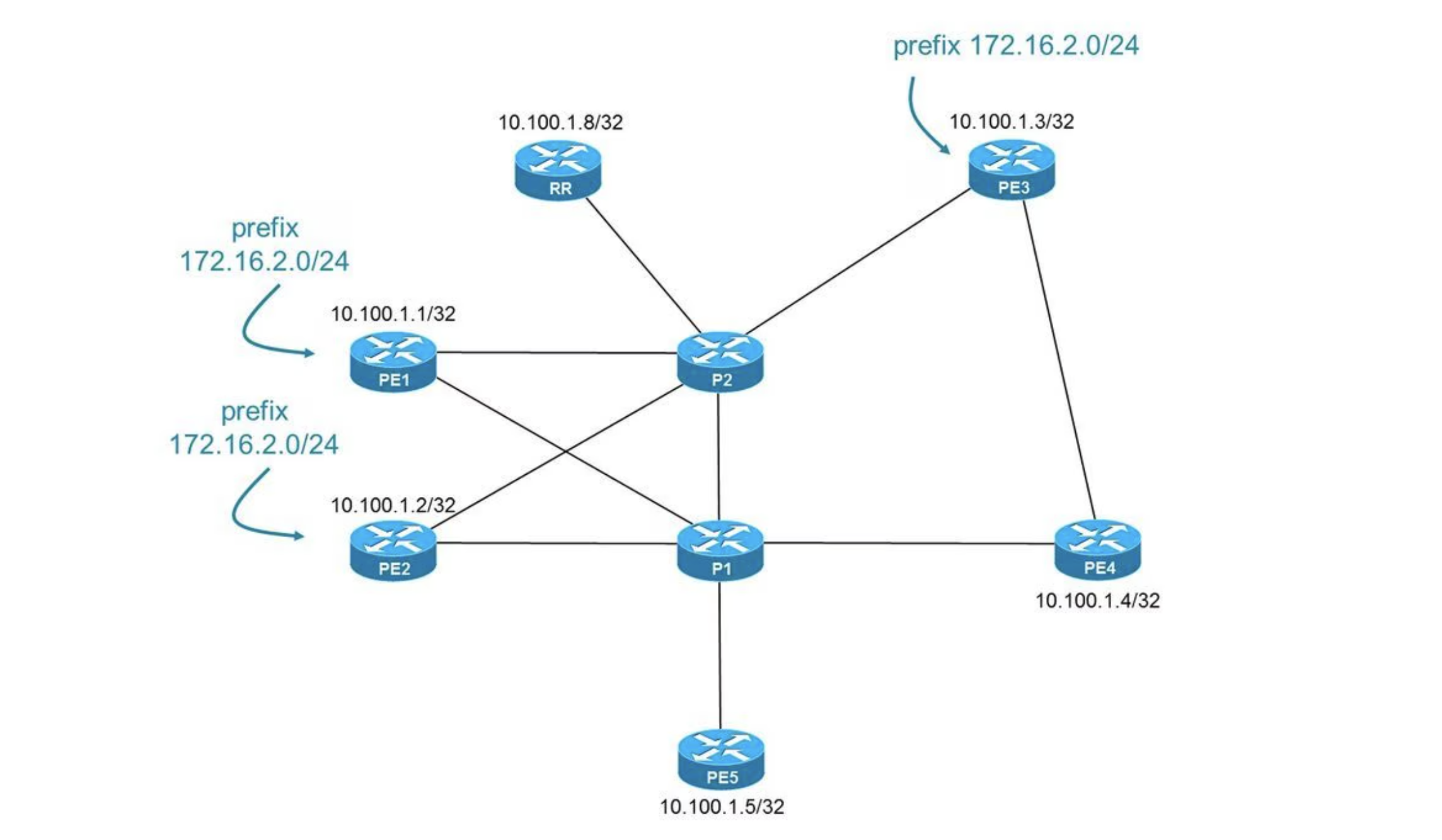
This approach, similar to OSPF's DR/BDR feature, provides large networks with added IBGP scalability. In a fully meshed IBGP network of 10 routers, 90 individual CLI statements (spread throughout all routers in the topology) are needed just to define the remote-AS of each peer: this quickly becomes a headache to administer. A RR topology could cut these 90 statements down to 18, offering a viable solution for the larger networks administered by ISPs.
A route reflector is a single point of failure, therefore at least a second route reflector may be configured in order to provide redundancy. As it is an additional peer for the other 10 routers, it comes with the additional statement count to double that minus 2 of the single Route Reflector setup. An additional 11*2-2=20 statements in this case due to adding the additional Router. Additionally, in a BGP multipath Environment this also can benefit by adding local switching/Routing throughput if the RRs are acting as traditional Routers instead of just a dedicated Route Reflector Server role.
In this way, the confederation preserves next hop, metric, and local preference information. To the outside world, the confederation appears to be a single AS. Confederations can be used in conjunction with route reflectors. Both confederations and route reflectors can be subject to persistent oscillation unless specific design rules, affecting both BGP and the interior routing protocol, are followed.
Process vs Thread
A process is a program that is actively running in memory, and it has its own memory space, program code, and system resources. Processes are independent of each other and don't share memory.
A thread is a lightweight unit of execution within a process that shares the process's memory space. Threads within the same process can communicate and coordinate more easily than processes.
- Process is a self-contained unit of execution that runs independently
- Thread is the smallest unit of execution within a process.
Switching threads doesn't require interaction with the OS, but switching processes does. A failure in one process doesn't directly affect other processes, but a failure in one thread can affect other threads in the same process. Processes are isolated and require less synchronization, but threads require careful synchronization due to shared resources.
-
Both processes and threads are independent sequences of execution. The typical difference is that threads (of the same process) run in a shared memory space, while processes run in separate memory spaces.
- Sibling "threads" (in most operating systems) share the same virtual address space, the same sockets and open files, all the same resources
- "Processes," on the other hand are isolated/protected from one another, and they share nothing except when they explicitly request to share some specific thing.
- In an OS that has both "processes" and "threads," a process often can be thought of as a container for one or more threads and, for all of the resources that they share.
- For example, Microsoft Windows supports preemptive multitasking, which creates the effect of simultaneous execution of multiple threads from multiple processes. On a multiprocessor computer, the system can simultaneously execute as many threads as there are processors on the computer.